

Before the arc strikes: How to predict and control stainless steel weld shrinkage
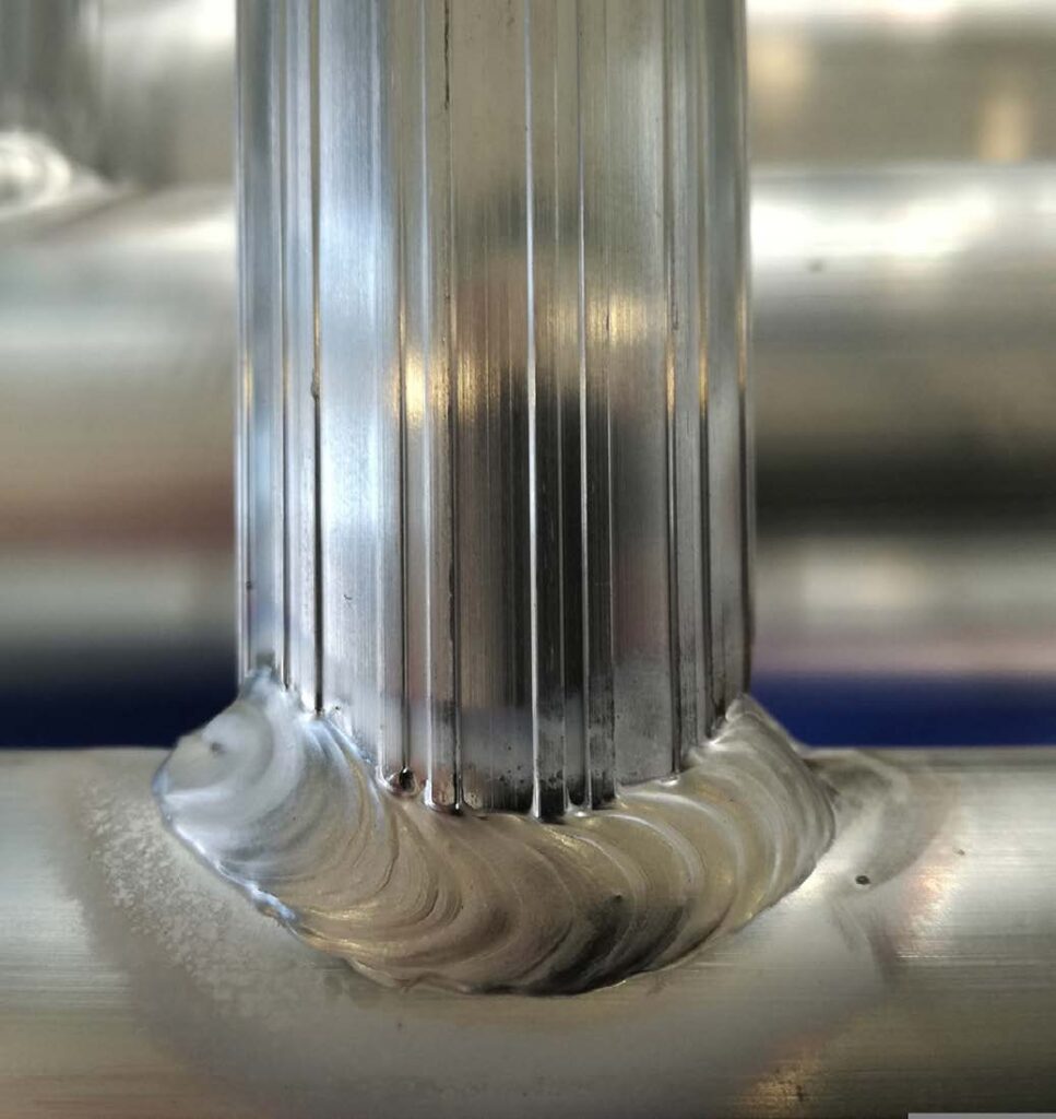
By calculating the likely movement before welding begins, fabricators can improve dimensional accuracy, reduce costly rework and prevent distortion from compromising the finished assembly.
In stainless steel fabrication, weld distortion should not be regarded as an unexpected event. It is a predictable consequence of localised heating, thermal expansion, weld metal solidification, contraction and restraint.
The challenge is particularly significant when welding austenitic stainless steels. These grades have relatively low thermal conductivity and a higher rate of thermal expansion than carbon steel. Heat remains concentrated around the weld for longer, while the material expands and contracts more significantly during the welding cycle.
A joint that is correctly aligned before the first arc is struck can therefore pull, bow or twist as it cools. In precision fabrications, even relatively small dimensional changes can move holes and flanges out of alignment, alter the profile of a component or create difficulties during final assembly.
Experienced fabricators consequently treat shrinkage as part of the production plan. Before welding begins, they consider how much filler metal will be deposited, how the joint geometry will contract, how the welding sequence will distribute heat and how clamps or fixtures will influence the final movement.
The rule of thumb every fabricator should know as a preliminary rule of thumb, fabricators can allow between 3 mm and 6 mm of movement across the joint for every 25 mm of weld throat thickness. On single-V groove joints, angular distortion can also develop rapidly and may fall in the range of 1° to 3° per weld pass.
These figures should be treated as workshop planning guides rather than substitutes for an engineering calculation or a representative welding trial. Actual movement will depend on the stainless steel grade, joint design, plate thickness, welding process, heat input, number and size of passes, restraint and overall stiffness of the fabrication.
The practical message is nevertheless important: stainless steel is unlikely to remain exactly where it was positioned unless the likely direction and magnitude of movement have been considered in advance.
Turning movement into a number
For a butt joint, transverse shrinkage can be estimated using the following engineering formula: ΔW=4.5×A÷t
Where:
ΔW is the estimated shrinkage across the joint
A is the weld-groove area in mm²
t is the plate thickness in mm
The formula provides a preliminary indication of the transverse contraction that could occur once the deposited weld metal and surrounding heat-affected zones have cooled.
It should be used as a planning tool and checked against the fabricator’s own production experience, welding procedure and, where tolerances are critical, a representative trial joint.
Start with the shape of the joint
The first step is to calculate the cross-sectional area of the weld groove. This is the space that will be filled with weld metal and is one of the principal factors influencing total shrinkage.
The joint can be divided into simple rectangles and triangles, with the areas then added together. For a simplified single-V joint, a practical estimate is:
A=(g×t)+[t2×tan (Ө ⁄₂)]
Where:
A is the groove cross-sectional area
g is the root gap
t is the plate thickness
Ө is the included groove angle
Once the groove area has been calculated, it can be entered into the shrinkage formula to provide a more realistic expectation of how far the joint may pull across the weld.
The calculation also highlights an important production consideration. An unnecessarily wide groove angle or excessive root gap increases the volume of filler metal required. This adds welding time and consumable cost while introducing more heat and greater shrinkage forces into the fabrication.
Reducing unnecessary weld-metal volume is therefore one of the most effective ways to limit distortion, provided that the joint continues to meet its design, strength and accessibility requirements.
Why the first pass matters most
Shrinkage is cumulative, but its effect is not necessarily distributed evenly between passes. The root and early filling passes can have a particularly significant influence on angular movement because they begin pulling the joint while the surrounding structure and deposited weld section remain relatively free to respond.
Later passes add more weld metal and increase the total transverse contraction. However, each pass is deposited onto an increasingly rigid weld section, and its effect will also depend on its position within the groove.
As a working allowance within the supplied methodology, the calculated result can be increased by about 10% for each additional pass beyond a single-pass weld. This should be treated as a preliminary planning adjustment rather than a universal prediction, as bead size, heat input and welding sequence can vary considerably between procedures.
The objective should be to use the fewest passes consistent with the approved welding procedure, required weld quality and metallurgical limitations of the grade being welded. Over-welding increases consumable use, labour time, heat input and the forces responsible for shrinkage.
Clamps reduce movement but not shrinkage forces
Most shrinkage calculations assume that the plates are free to move. In a workshop, however, components are frequently restrained using clamps, jigs, strong backs or dedicated fixtures.
As a preliminary workshop guide:
- An unclamped or freely moving joint may experience close to 100% of the calculated movement.
- A lightly clamped joint may display about 60% to 70% of the calculated movement.
- A heavily fixtured joint may display about 30% to 40% of the calculated movement.
These percentages are indicative only. The actual result depends on fixture stiffness, tack-weld placement, component geometry, welding sequence and the point at which the restraint is released.
Importantly, restraint does not eliminate shrinkage. It changes the way the fabrication responds to it. If a component cannot contract freely, part of the contraction is converted into residual stress.
When the clamps are removed, some delayed movement may still occur. In highly restrained fabrications, significant stresses may remain locked into the component, potentially affecting subsequent machining, assembly or service performance.
Fixtures should therefore form part of a broader distortion-control strategy rather than being used to compensate for excessive heat input, over-welding or an unsuitable joint design.
Do not overlook longitudinal pull
Transverse shrinkage occurs across the weld, while longitudinal shrinkage shortens the component in the direction of the weld.
Longitudinal movement is generally smaller than transverse shrinkage, but it can still cause bowing, end pull and alignment problems on long seams. As a broad workshop guide, longitudinal movement of approximately 3 mm to 6 mm along a long weld seam may be sufficient to affect a precision fabrication.
The actual amount will depend on the seam length, weld cross-section, heat input, component stiffness and position of the weld relative to the neutral axis of the assembly.
A weld positioned away from the neutral axis can introduce bending as well as shortening. Similarly, a series of unbalanced welds on one side of a fabrication can create cumulative distortion even when the movement associated with each individual weld appears relatively small.
Long seams should therefore be assessed as part of the complete structure rather than considered in isolation.
Plan the weld before the metal moves
The most effective distortion control begins before welding. The fabricator should confirm the joint type, plate thickness, groove angle, root gap, root face, welding process, heat input and anticipated number of passes before deciding how the assembly should be restrained and sequenced.
Depending on the design and application, practical control measures can include:
- Reducing unnecessary weld-metal volume
- Using double-V joints on thicker sections where both sides are accessible
- Presetting components opposite to the expected movement
- Applying balanced or symmetrical welding sequences
- Using back-step, skip or block welding techniques where appropriate
- Alternating welds around the neutral axis
- Controlling heat input and interpass temperature
- Using correctly positioned tack welds and strongbacks
- Welding smaller subassemblies before completing the main structure
- Conducting a representative trial before repeat production
The correct approach will vary from one fabrication to another. Thin sheet may be particularly vulnerable to buckling, while thick and highly restrained sections may retain significant residual stress even when visible distortion is limited.
From calculation to workshop control
Shrinkage calculations do not guarantee a final dimension. Their value lies in providing a rational starting point for the fabrication plan.
Once the likely direction and scale of movement have been estimated, the fabricator can decide whether the joint requires a modified root opening, preset, alternative sequence, different fixturing arrangement or representative trial.
Production results should also be recorded. Measuring the actual movement from the first completed fabrication creates valuable workshop data that can be used to refine allowances for subsequent units produced with the same material, joint configuration, welding procedure and restraint.
This turns distortion control from a reactive correction process into an increasingly accurate production system. Correcting a distorted stainless steel assembly after welding can be costly and technically difficult. Mechanical straightening may damage the surface, while thermal correction must be carefully controlled to avoid further distortion, metallurgical changes, residual stress or impaired corrosion performance.
The strongest result is therefore achieved before the first arc is struck. By calculating the weld volume, predicting the likely direction of contraction and designing the welding sequence around that movement, fabricators can improve dimensional control, reduce rework and produce more consistent stainless steel assemblies.
Stainless steel will always expand and contract beneath the welding arc. The fabricator’s advantage lies in knowing where that movement is likely to go, and planning the job so that the finished component ends up exactly where it should.