

Straight first time: How welding planning prevents costly distortion
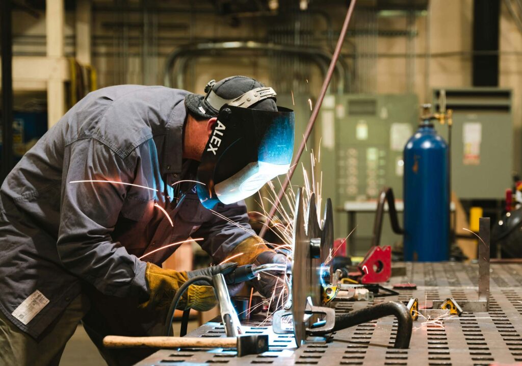 A practical fabrication case study shows how joint design, welding sequence, restraint and heat control can keep stainless steel assemblies within tolerance.
Every fabricator knows the frustration: the bead looks good, the joint is sound and the assembly remains correctly aligned, until it cools and pulls itself out of shape.
Weld distortion is more than a cosmetic problem. It can compromise fit-up, dimensional accuracy and productivity, while severe distortion may affect the performance or structural integrity of the completed weldment. Correcting it adds time, labour and cost, with no guarantee that the original tolerances will be fully restored.
Consider a typical workshop challenge: fabricating a stainless steel panel with welded stiffeners and several attached brackets. The welds are individually straightforward, but they are positioned on one side of the plate. If they are then welded to the plate one after the other, their combined shrinkage can bow the panel and pull its connection points out of alignment.
The solution begins before welding with a production plan that treats distortion as a predictable engineering response.
Why weldments move
Metal expands when heated and contracts as it cools. During welding, the weld pool and surrounding base metal experience rapid, highly localised heating. As the weld solidifies and cools, it attempts to shrink, but the colder surrounding material restrains that contraction.
This creates residual stress within the weldment.
Once clamps, fixtures or strongbacks are removed, some of the stress may be released as movement, leaving the component shorter, bowed, twisted or angularly distorted.
Austenitic stainless steels are particularly sensitive because they combine relatively high thermal expansion with low thermal conductivity. Heat remains concentrated around the joint, increasing the need for disciplined heat and sequence control.
Start by reducing weld volume
For the panel fabrication, the first step is to confirm that every weld is correctly sized. Oversized fillet welds introduce unnecessary filler metal, heat and shrinkage force without providing a corresponding engineering benefit.
Correct fit-up is equally important. Excessive root gaps and unnecessarily wide groove angles increase the volume of deposited metal, consumable use and welding time. On thicker plate, a double-V preparation may require less filler metal and provide better stress balance than a comparable single-V joint, provided both sides are accessible.
Where the design permits, intermittent welds can replace continuous seams on stiffeners and similar attachments. This can substantially reduce the total deposited weld metal while still providing the required strength.
Balance forces around the neutral axis
The position of a weld determines how much leverage its shrinkage force has over the component. Welds located close to the neutral axis generally create less bending, while welds positioned far from it can generate significant angular movement.
In the panel example, completing all the welds on one side before beginning elsewhere would concentrate heat and contraction in one area. A more effective sequence alternates between opposing sides and different areas of the assembly, allowing one shrinkage force to counter another.
Subassemblies should also be planned so that each stage remains as balanced as possible. The aim is not merely to complete welds conveniently, but to distribute heat and contraction throughout the structure.
Use sequence to control movement
A planned sequence can prevent local shrinkage from accumulating into large-scale distortion. Practical options include alternating sides of a joint, staggering welds across the fabrication and welding towards the unrestrained portion of a member.
Backstep welding may also be useful. With this technique, the overall weld progresses in one direction while each short bead is deposited in the opposite direction.
It can help distribute contraction, although it is not suitable or economical for every joint.
The number of passes should be kept to the minimum permitted by the approved welding procedure and joint requirements. Multiple passes create repeated heating and cooling cycles, with each pass adding further shrinkage.
Preset for the expected result where the likely direction of movement is known, the components can be preset, pre-bent or pre-sprung in the opposite direction. Welding shrinkage is then used to pull the assembly towards its required final position.
The correct preset may be determined from previous production data, a representative trial weld or procedure development. For repeat fabrication, recording the actual movement of the first unit enables the workshop to refine the preset and sequence for subsequent assemblies.
Identical weldments may also be clamped back to back so their shrinkage forces oppose one another. They should remain restrained until they have cooled sufficiently to minimise movement when the clamps are released.
Restraint is not a complete solution
Clamps, fixtures, jigs and strongbacks help maintain fit-up and alignment during welding. Strongbacks are particularly useful on butt-welded plate, where clips and wedges can hold plate edges in position throughout the welding cycle.
However, restraint does not remove shrinkage. It can convert visible movement into residual stress. Some movement may occur after the restraint is released, particularly if the component remains hot.
Fixtures should therefore support a sound welding strategy rather than compensate for over-welding, poor fit-up or an unbalanced sequence.
On thin sheet, water-cooled or heat-sink fixtures can combine restraint with rapid heat removal. These systems require careful application to avoid excessively rapid cooling or adverse effects on weld quality and metallurgy.
Control heat without compromising the procedure
Distortion control is closely linked to heat input, but “less heat” does not simply mean welding as quickly as possible. Current, voltage, travel speed, electrode size, deposition rate and welding position must remain within the qualified procedure.
Positioners can increase flat-position welding, allowing efficient deposition and consistent travel. The objective is to deposit the required weld metal efficiently without overheating a large surrounding area.
Peening may be permitted in selected applications to counter weld contraction, but it requires engineering approval and must comply with the applicable procedure. Root and final passes are generally excluded because of cracking and inspection concerns.
Thermal stress relief may reduce residual stresses in suitable weldments, but stainless steel grade, component design and service requirements must be considered before any heat treatment is specified.
The workshop control plan
Before striking the arc, the fabrication team should confirm that it has:
- Avoided over-welding and minimised groove volume
- Achieved consistent fit-up and root gaps
- Used intermittent welds where permitted
- Balanced welds around the neutral axis
- Planned an alternating, symmetrical welding sequence
- Limited the number of passes
- Selected a qualified, controlled heat-input procedure
- Used positioners where these improve welding efficiency
- Provided appropriate clamps, fixtures or strongbacks
- Preset components for predictable shrinkage
- Planned subassembly and final-assembly sequencing
- Allowed the fabrication to cool sufficiently before releasing restraint
Distortion cannot be eliminated entirely, but it can be controlled. In the panel example, reducing weld volume, alternating the stiffener welds, presetting the plate and maintaining restraint during cooling prevents individual shrinkage forces from accumulating in one direction.
The result is a straighter assembly, more accurate connections and substantially less corrective work. The central lesson is simple: distortion control belongs in the welding plan, not in the repair bay.